Laser-assisted bend angle measurement systems
LaserCheck are fully-automatic, laser-assisted bend angle measurement systems for press brakes. Irrespective of the properties or thickness of the material, the LaserCheck enables an exact determination of the bend angle with an accuracy of better than 0.1°. This represents precision which has never been available before.
Read MoreWhat is a laser-assisted bend angle measurement system?
Why need a laser-assisted bend angle measurement system?
Manufacturing sheet metal parts with accurate bending angles that are kept constant all times often meets a problem during the actual production process: different parameters in material thickness and stresses
Browse MoreWorking principle
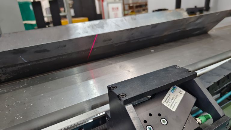
- The bending angle is measured by scanning the projection of the laser beam on the surface of the sheet metal with the integrated camera.
- The angle between the laser and the camera axis enables an angle measurement.
- With a second sensor at the opposite site the bending angle is calculated.
Characteristics
- The LaserCheck sensor is mounted on the press brake, below the die, with an angle of 35° - 55° to the vertical.
- The working distance (between sensor and sheet) is 90 - 2000 mm, depending on the sensor type.
- It is moveable along the die either manually or automatically.
- Due to its mounting position the measuring range is 30° - 180° (bending angle).
- For each measuring position 2 sensors are used. Motorized sensors enable an independent correction of the beam to compensate angle differences in long bends
- Measurement in the machine center allows crowning correction (depending to the control).
Designed for industrial applications
- The sensors in the LaserCheck product range are especially designed for sheet metal applications.
- Due to their robust construction and user friendly technical features, they achieve precise measurement results even in harsh ambient conditions.
- By carefully miniaturising every component, we have created small and robust sensors that fit on any press brake.
Integration into controls
- Serial Interface for Amada controls.
- Combined TCP/IP-Modbus interface for Delem controls. The angles are sent to a DM-101RS module via Modbus. Force sensors are connected to an analogue input of the module.
- Modbus for the hand-wheel interface of Delem DA66T und DA69T.
- Open TCP/IP interface for Cybelec VisiTouch, ESA and Robosoft controls.
Real time measurement
- The fast GigE cameras inside the LaserCheck sensors allow real time measurement with refresh rates up to 100Hz per sensor.
- This results in 200 interpolated angle measurements every second.
- USB sensors are supporting refresh rates of 50Hz each.
- Bending process is not interrupted
- Fast bending process
- Spring-back measurement without force measurement
Calibration & Accurarcy
- The sensor accuracy is better than ±0.1°.
- The bending accuracy is influenced by the control, the machine accuracy, the tools and the material.
- To increase the bending accuracy the sensors can be calibrated after mounting, so the mounting tolerance is reduced.
- All sensors are pre-calibrated in order to work with good results without the need of a calibration after mounting.
- Only the mounting angle must be defined.
- Linear error corrections for different measuring situations can be input by the machine user.
Main Model
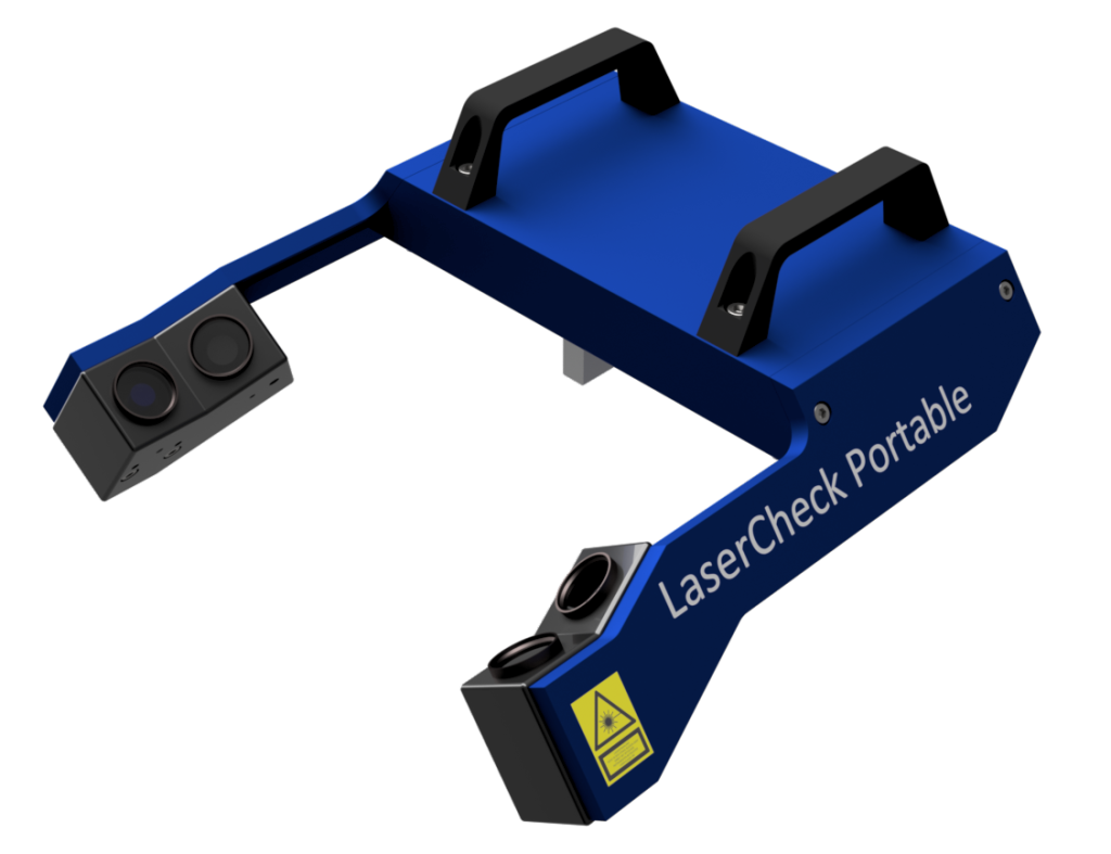
LaserCheck Portable
LC Portable is a bending angle measurement system for retrofitting press brakes with die sizes from 6mm to 60mm. It is the ideal solution for small machines up to 3m width with Delem-, ESA- or Cybelec controllers. It is fixed in the die holder with magnets and is shipped fully wired and calibrated.
- Design:ALL IN ONE – Full measurement system in one device
- Measurement range :Bend angle 30-180°
- Tool area:Die width V6-V60 Die height 55-85 or 85-110
- Working distance:Working distance between 90 and 220mm
- Integration:Can be connected to machines via TCP/IP or Modbus (Cybelec, Delem, ESA)
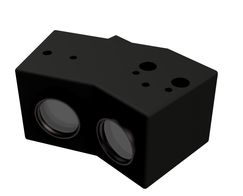
LaserCheck 10L
The laser-assisted bend angle measurement system LaserCheck 10L works without physical contact. Existing press brakes can be upgraded with LaserCheck 10L without modifications to stamps or die.Max. cable length of 5m at machine length of approx. 3m
- Design: Small and robust build to save space.
- Integration:Connecteion to machines via TCP/IP, Modbus, RS232, EtherCAT (Amada, Bystronic, Cybelec, Delem, ESA, Robosoft, Stepautomation)
- Tool area: Die width V6-V60 Die height 55-85 or 85-110
- Working distance:Working distance between 100 and 160mm
- USB-cameras:max. cable length 5m
- Measurement range:Bend angle 30-180°
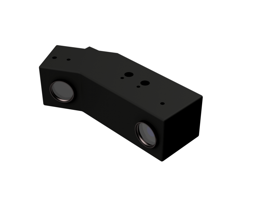
LaserCheck 12
The laser-assisted bend angle measurement system LaserCheck 12 works without physical contact. Existing press brakes can be upgraded with LaserCheck 12 without modifications to stamps or die. Due to the working range between 165 and 380mm, the sensor is especially designed for large machines.
- Design: Small and robust build to save space.
- Integration:Connecteion to machines via TCP/IP, Modbus, RS232, EtherCAT (Amada, Bystronic, Cybelec, Delem, ESA, Robosoft, Stepautomation)
- Real-time measurement: Frame rate up to 100Hz per sensor
- Tool area: Die width V6-V100 Die height 55-85 or 85-110
- Working distance: Working distance between 165 and 380mm
- Accuracy: Very high accuracy (better than +/- 0.1°)
- Gigabit-Ethernet: Cable length of up to 50m
Main Operation Structure
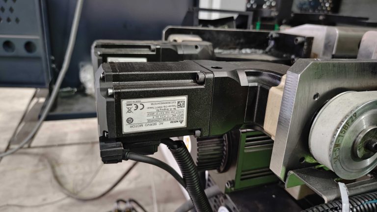
Servo Motor
- The servo motors on both sides are responsible for the movement of the laser detection device, featuring high movement speed and precise positioning.
- The motor assembly is mounted on the vertical plate via screws and drives the first transmission assembly through a timing belt.
Mechanical Installation Components
- Vertical Plate: Serving as a basic supporting structure, it is used to install components such as motor assemblies, transmission assemblies, and linear guides.
- Linear guides are installed on the front and rear sides of the vertical plate, and their sliding carriages are connected to the mounting supports via the second connecting seats, ensuring the straightness and stability of the laser angle detector during movement.
- The transmission assemblies are divided into two types (Assembly 1 and Assembly 2), which include components such as transmission shafts. They are connected to the motor's timing belt, transmit power, and drive the detector to move left and right for full-length detection.
Installation Bracket
- A 45° mounting surface and holes (for installing the laser angle detector) are machined on the upper part, while a connecting surface and holes are machined on the lower part, which are connected to the second connecting seat via screws.
- Protective Cover: In the plate measuring device, a transparent cover is placed over the inner frame to protect the internal line laser and camera from damage caused by dust and oil stains.